Power and electrical design
Power architecture: the decision that constrains everything
Your power tree decides your product's performance, cost and timeline.
By Peter Sords··3 min read
The short answer
Power architecture is the set of early decisions about rails, regulator topologies, sequencing, protection and heat removal, and it constrains a product's performance, thermal behavior, EMI, battery life, cost and compliance. The common failures are linear regulators overheating in sealed enclosures, unanalyzed load steps, unprotected power paths, ignored input transients, and converter losses sized from datasheet DCR instead of real AC loss.
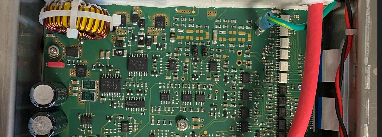
Your power architecture is the one decision that touches everything in your product: performance, thermal, EMI, battery life, cost, regulatory compliance, and reliability.
Get it wrong early, and every other decision gets harder.
Power is architecture, not a subsystem
It's tempting to treat power as plumbing: pick a regulator for each voltage and move on. But every rail, every regulator and every converter affects signal integrity and EMI. A switching regulator is a noise source, and it often sits on the same board as your most sensitive measurement.
Power sequencing requirements cascade through the entire system. The order in which rails come up and go down constrains your processor, your peripherals, and the firmware that has to manage them.
And thermal management is primarily a power management problem. Every watt your conversion stages waste becomes heat that has to get out of the enclosure.
Four mistakes that show up late
- LDOs where switchers are needed. A linear regulator turns the full voltage drop times the load current into heat. On an open bench that's a warm part. In an enclosed product it can be the reason the product overheats.
- No load-step analysis. When a high-current peripheral switches on, the rail droops. If nobody analyzed that transient, the first sign is a reset that only happens under load.
- Single points of failure with no protection or monitoring. One power path, nothing to limit a fault, and no way to see a rail in trouble before the product stops.
- Ignoring input transients. Hot-plug, load dump and ESD on the power pins are what real cables and real connectors deliver. A design that has only ever seen a bench supply hasn't met them yet.
The number on the datasheet is not the loss
The same blind spot shows up in parts selection. Take the inductor in a buck converter. The number everyone designs around is DCR, the winding's DC resistance. At DC, it's the whole story.
Your converter doesn't run at DC.
At switching frequency the winding sees skin effect and proximity effect, the air gap throws a fringing field straight into the copper, and the core adds loss of its own. Proximity effect alone can raise effective winding resistance by two to five times at typical 100 to 500 kHz buck operating points.
So I don't size magnetics off DCR. I pull the AC resistance at the actual switching frequency, add the core loss, run it against the real ripple current, and only then trust the efficiency curve.
It matters because an 8 °C unmodeled rise can eat most of your thermal margin in a sealed enclosure, and that's the gap between a passing reliability test and a field return. Catching it in simulation costs an afternoon. Catching it in production costs a board respin, a new inductor footprint, and a thermal re-qualification.
A useful tell: if the inductor is the hottest single component on the board, you are almost certainly under-modeling AC loss, not under-sizing saturation current.
The power architecture checklist
Before layout, not after the first brownout:
- Map every rail. Voltage, current, noise sensitivity, and sequencing requirements.
- Choose a topology per rail. LDO, buck, boost or SEPIC, chosen on efficiency and noise.
- Analyze load steps and transient response. Do it before layout, while a fix is still a schematic change.
- Plan the thermal path for every converter. Use real loss numbers, including AC winding loss and core loss, not DCR alone.
None of this takes long at the start. Power is the decision that's expensive to unwind once the schematic is frozen.
About the author
Peter Sords is the founder and Director of Engineering at Kyros Engineering, a senior-led electronics, PCB, embedded firmware and hardware product development firm in Cleveland, Ohio. More about Kyros
Frequently asked
When should I use a switching regulator instead of an LDO?
When the voltage drop times the load current is more heat than the product can shed. An LDO turns that difference into heat, which is fine on an open bench and a problem in a sealed enclosure. Switchers are more efficient but are noise sources, so the choice is made per rail on efficiency and noise.
Why does a buck converter inductor run hotter than the DCR calculation predicts?
Because DCR only accounts for DC loss. At switching frequency, skin and proximity effects, fringing from the air gap, and core loss all add to it. Proximity effect alone can raise effective winding resistance two to five times at typical 100 to 500 kHz operating points.
What should a power architecture review cover before PCB layout?
Every rail's voltage, current, noise sensitivity and sequencing; the topology chosen for each rail; load-step and transient response; protection against input transients; and a thermal path for every converter, sized from real loss numbers.